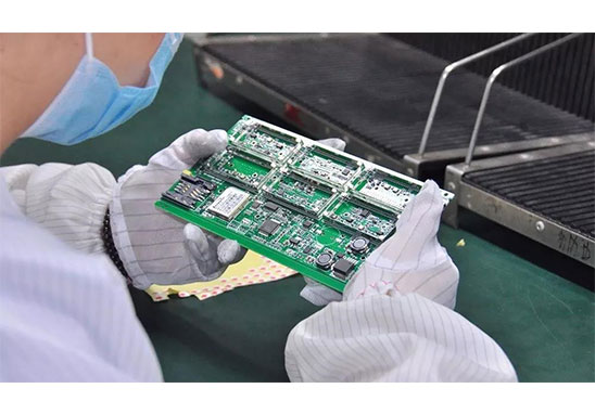
The core of electronic equipment is the Printed Circuit Board(PCB), and the circuit board is composed of a large number of various types of electronic components. If the equipment fails or has a short circuit, mostly which is caused by the failure or damage of the electronic components.
1. Measure The Polarity of Each Rectifier Bridge Pin
The multimeter is set to R×1k block, the black test lead is connected to any pin of the bridge stack, and the red test lead measures the remaining three pins successively. If the reading is infinite, the black test lead is connected to the output positive pole of the bridge stack. If the reading is 4~10kΩ , then the pin connected to the black test pen is the output negative pole of the bridge stack, and the other two pins are the AC input terminals of the bridge stack.
2. Check The Quality of The Crystal Oscillator
First use a multimeter (R×10k block) to measure the resistance value at both ends of the crystal oscillator. If the resistance value is infinite, it means that the crystal oscillator has no short circuit or leakage; Then insert the test pen into the mains jack, and pinch any pin of the crystal oscillator with your fingers, touch the other pin to the metal part at the top of the test pen, if the neon bulb of the test pen turns red, it means the crystal is good; If the neon bulb does not light up, it means the crystal is damaged.
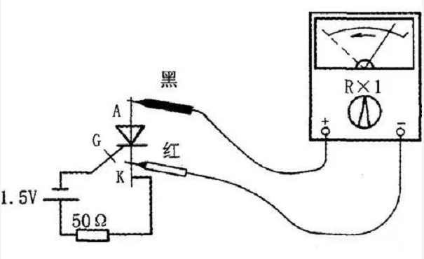
3. Unidirectional Thyristor Detection
Use the R×1k or R×100 gear of the multimeter to measure the forward and reverse resistance between any two poles. If the resistance of a pair of poles is found to be low resistance (100Ω~lkΩ), then the black test pen is connected to the control pole, the red test pen is connected to the cathode, and the other pole is the anode. The thyristor has three PN junctions in total, and we can judge its quality by measuring the size of the forward and reverse resistances of the PN junction. When measuring the resistance between the control electrode (G) and the cathode (C), if the forward and reverse resistances are both zero or infinite, it indicates that the control electrode is short-circuited or open; measure the resistance between the control electrode (G) and the anode (A). When measuring the resistance, both the forward and reverse resistance readings should be large; when measuring the resistance between the anode (A) and the cathode (C), both the forward and reverse resistances should be large.
4. Polarity Recognition of Triac
The triac has a main electrode 1, a main electrode 2 and a control electrode. If the resistance between the two main electrodes is measured with a multimeter R×1k, the reading should be approximately infinite, and the positive and negative values between the control electrode and any one of the main electrodes. The resistance reading is only a few tens of ohms. According to this characteristic, we can easily identify the gate electrode of the triac by measuring the resistance between the electrodes. And when the black test lead is connected to the main electrode 1. The forward resistance measured when the red test lead is connected to the control electrode is always smaller than the reverse resistance, so we can easily identify the main electrode 1 and the main electrode 2 by measuring the resistance.
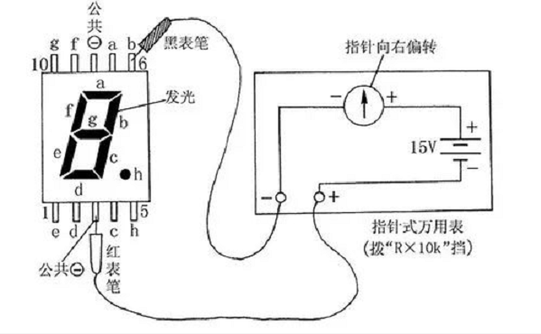
5. Check The Quality of The LED Digital Tube
First set the multimeter to R×10k or R×100k block, then connect the red test pen to the “ground” terminal of the digital tube (take the common cathode digital tube as an example), and connect the black test pen to the other terminals of the digital tube in turn. It should be illuminated separately, otherwise the digital tube is damaged.
Advantages of PCB Assembly In Grande
1. Highly Professional: Grande focuses on PCBA samples, small and medium batches; For 2 Layer Simple Sample PCBA, Grande promises to deliver within 3-7 working days after the materials are confirmed to be OK.
2. Professional Equipment: Advanced equipment tailored for sample and small and medium batch production, and can be pasted with 0201, BGA spacing 0.3MM, QFN, CSP, CON and other components.
3. Professional Technology: 100% of technical backbones have more than 5 years of work experience, and 85% of front-line operators have more than 3 years of work experience.
4. Grande implements the 5S and 6σ concepts in daily operations, and it is expected that the shipment will be checked at least 7 times.
5. Grande promises that the soldering pass rate is above 99%. If the customer finds soldering defects, the company promises to repair it free of charge.