The core of electronic equipment is the circuit board, and the circuit board is assembled by welding various types of electronic components. If the equipment fails or short-circuits, most of the reasons will be caused by the failure or damage of the electronic components.
1.Testing skills of circuit board components
Measure the polarity of each leg of the rectifier bridge
The multimeter is set to R×1k block, the black test lead is connected to any pin of the bridge stack, and the red test lead measures the remaining three pins one after the other. If the readings are all infinity, the black test lead is connected to the output positive pole of the bridge stack, if the reading is 4~10kΩ , The pin connected to the black test lead is the output negative terminal of the bridge stack, and the remaining two pins are the AC input terminals of the bridge stack.
2. Judge the quality of the crystal oscillator
First use a multimeter (R×10k block) to measure the resistance value at both ends of the crystal oscillator. If the resistance value is infinite, it means that the crystal oscillator has no short circuit or leakage; then insert the test pencil into the mains socket and pinch any pin of the crystal oscillator with your fingers , Touch the other pin to the metal part on the top of the test pencil. If the neon bulb of the test pencil turns red, it means that the crystal is good; if the neon bulb is not bright, it means that the crystal is damaged.
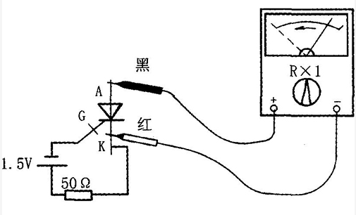
3. Unidirectional thyristor inspection
The R×1k or R×100 block of a multimeter can be used to measure the forward and reverse resistance between any two poles. If the resistance of a pair of poles is found to be a low resistance value (100Ω~lkΩ), then the black test pen is connected to the control The red test lead is connected to the cathode, and the other is the anode. The thyristor has 3 PN junctions, and we can judge its quality by measuring the forward and reverse resistance of the PN junction. When measuring the resistance between the control electrode (G) and the cathode (C), if the forward and reverse resistances are both zero or infinite, it indicates that the control electrode is short-circuited or open; measuring the resistance between the control electrode (G) and the anode (A) For resistance, both the positive and reverse resistance readings should be large; when measuring the resistance between the anode (A) and the cathode (C), both the positive and reverse resistances should be large.
4. Polarity recognition of bidirectional thyristor
The bidirectional thyristor has a main electrode 1, a main electrode 2 and a control electrode. If the resistance between the two main electrodes is measured with a multimeter R×1k block, the reading should be approximately infinite, and the positive and negative between the control electrode and any one of the main electrodes The resistance reading is only a few tens of ohms. According to this characteristic, we can easily identify the control electrode of the bidirectional thyristor by measuring the resistance between the electrodes. When the black test lead is connected to the main electrode 1. The forward resistance measured when the red test lead is connected to the control electrode is always smaller than the reverse resistance. Based on this, we can easily identify the main electrode 1 and the main electrode 2 by measuring the resistance.
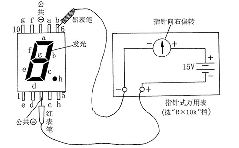
5. Check the quality of the light-emitting digital tube
First set the multimeter to R×10k or R×100k, then connect the red test pen to the “ground” terminal of the digital tube (take the common cathode digital tube as an example), and then connect the black test pen to the other terminals of the digital tube. They should emit light separately, otherwise the digital tube is damaged.