Grande has its own PCB Fctory and SMT Assembly factory, which can provide FPC Flex PCB Fabrication and FPC PCBA Manufacturing services!
Flex PCB Assembly Capability
Number of Rigid-Flex PCB / Flex PCB Layers: 10/6;
Minimum Trace Width & Spacing: 3/3mil;
Board Thickness Aperture Ratio: 12:1;
Distance From Hole to Conductor: 6mil;
Impedance Tolerance (Ω): 10%;
Surface Finish: Chemical immersion gold, immersion tin, HASL, hard gold plating, soft gold, silver paste, etc.
Common Types of Flex PCB
At present, Flex PCB has four types: Single-Sided FPC, Double-Sided FPC, Multilayer Flex PCB & Rigid-Flex PCB.
1. Single-Sided FPC: The lowest cost printed circuit board that do not require high electrical performance. In Single-Sided FPC Layout, it has a layer of chemically etched conductive patterns, and the conductive pattern layer on the surface of the flexible insulating substrate is a rolled copper foil. The insulating substrate can be polyimide, polyethylene terephthalate, aramid cellulose ester and polyvinyl chloride.
2. The Double-Sided FPC: A conductive pattern made by etching on both sides of the insulating base film. The metallized hole connects the patterns on both sides of the insulating material to form a conductive path to meet the design and use function of flexibility. The coverlay can protect single and double-sided traces and indicate where the components are placed.
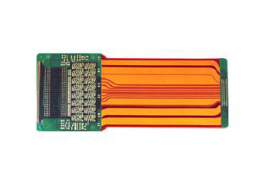
3. Multiayer Flex PCB: To laminate 3 or more layers of single-sided or double-sided FPC together, and form metallized holes by drilling and electroplating to form conductive paths between different layers. In this way, no complicated soldering process is required. Multilayer circuits have huge functional differences in terms of higher reliability, better thermal conductivity and more convenient assembly performance. When designing the layout, the mutual influence of assembly size, number of layers and flexibility should be considered.
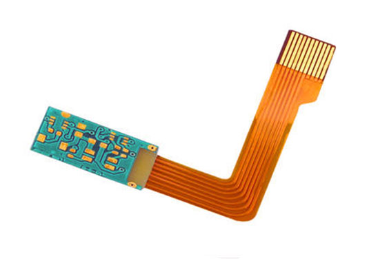
4. The traditional Rigid-Flex PCB: Be composed of rigid and flexible substrates selectively laminated together. The structure is tight, and the metallized hole L forms a conductive connection. If a printed board has components on the front and back sides, rigid flexible circuit boards are a good choice. But if all the components are on one side, it will be more economical to choose a double-sided flexible circuit board and laminate a layer of FR4 reinforced material on its back.
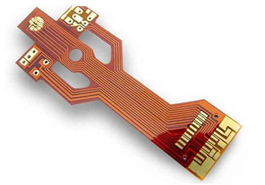
5. The FPC flex circuit board with hybrid structure is a multi-layer board, and the conductive layer is made of different metals. An 8-layer board uses FR-4 as the inner layer medium and polyimide as the outer layer medium. Leads extend from three different directions of the main board, and each lead is made of a different metal. Constantan alloy, copper and gold are used as independent leads. This kind of hybrid structure is mostly used in the relationship between electrical signal conversion and heat conversion and under low temperature conditions where the electrical performance is relatively harsh. It is the only feasible solution. It can be evaluated by the convenience of the internal connection design and the total cost to achieve the best performance-price ratio.